Episode 1 A Taste of Color
In our other series on microbit, we used a timer example to illustrate the model-driven approach of software design. We introduced a simple reusable statechart framework on which we build our application using the concept of states, events and timers.
In that example we have 25 LEDs to control with the shortest blinking period of 100ms. Its logic is modest, supporting timer set, start, pause, stop and alert. While there are benefits of using statecharts, one may wonder whether it is necessary to use statecharts for such a simple program. After all we could write a program in less code with a basic loop, some flags and pause() function calls.
As in many real-life projects, requirements do change and the system logic is likely to get more complicated. Instead of using the built-in LED display on the microbit, how about we switch to some of these RGB LED panels?
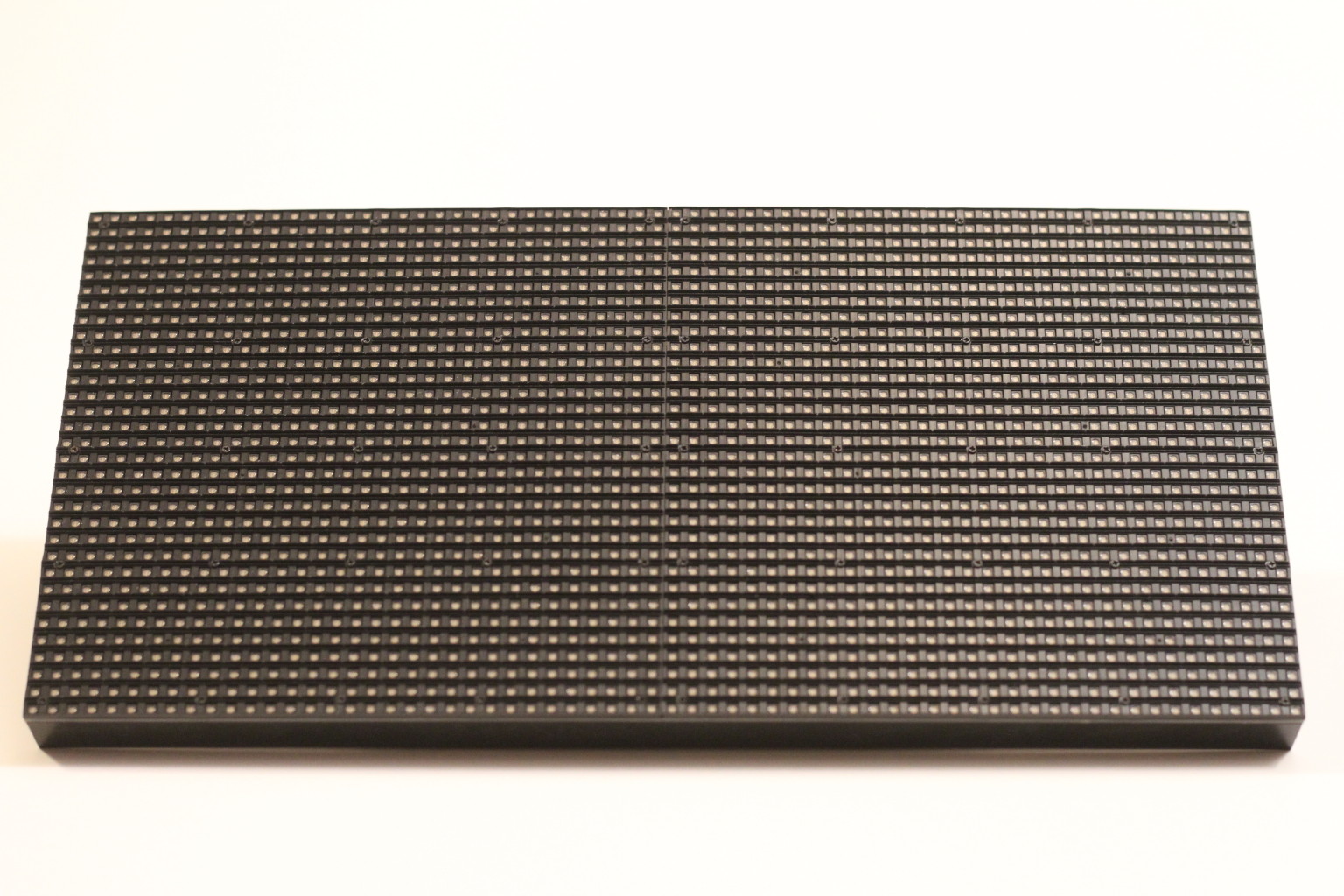
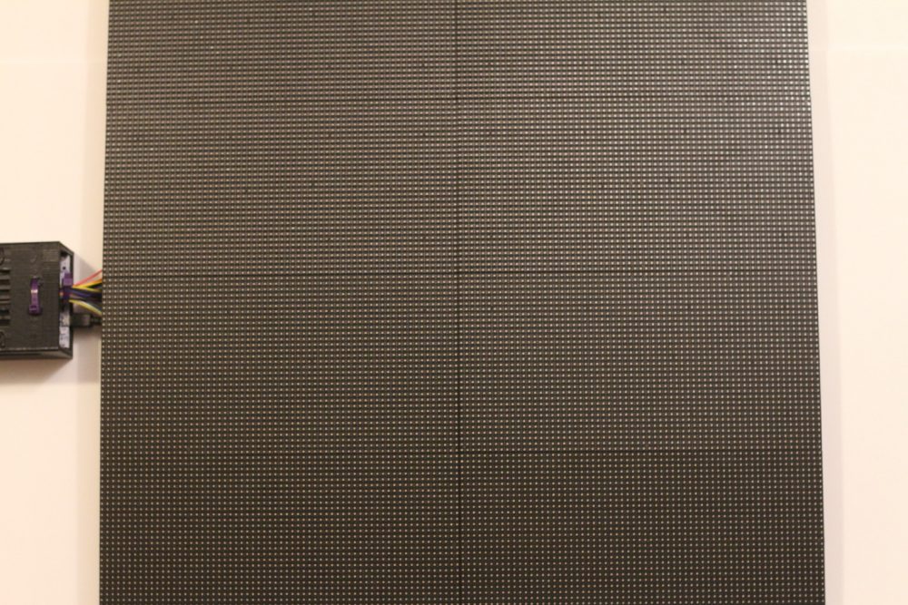
Each panel contains 64×32 (2,048) RGB LEDs. Since each RGB LED is made with three individually controlled LEDs, a red, green and blue LED, there are altogether 6,144 individual LEDs on each panel. Wait. It’d be nice to connect 8 panels together to form an impressive 128×128 panel with 49,152 individually controlled LEDs, which looks like this one below.
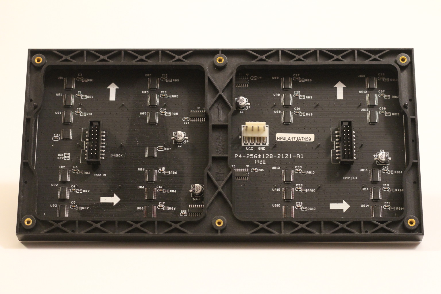
The hardware design of these LED panels is very simple, containing “glue logic” ICs such as demultiplexers and shift registers. As a result, they are very cost-effective and are popular in building giant displays in shopping malls and sport stadiums. (Note – these are not WS2812 color LEDs with built-in controllers.)
To save power and circuit complexity, only two rows of LEDs on each panel are turned on at any time. To show a complete image, an external controller must constantly refresh the display by scanning through all the rows. Due to the high data rate, it typically calls for an FPGA or ASIC, similar to those found on LCD or OLED module.
Since our focus is embedded and real-time software, it would be much more interesting to control these panels directly without any off-the-self controller boards. We would need to drive the row address, RGB data, pixel clock, latch and enable pins precisely in order to show the correct color at each pixel.
Obviously there are plenty existing projects using Arduino or Raspberry Pi. So why do we reinvent the wheel here? What are the new ideas?
What distinguishes this project from others is the general use of model-driven approach and statecharts in software design and construction. We aim at providing practical examples of applying statecharts to real-life projects – something more complicated than a toaster (with on/off states) but less abstract than a rocket launcher or air-traffic controller. We will show you how you may use statecharts in designing a DMA-based UART driver, an interactive console, a high-level GUI manager, and of course a DMA-based data/clock driver for LED panels.
As memory and processing requirements increase, we will migrate the processor platform from Microbit to STM32H743 Nucleo. Despite the hardware change, the underlying statechart modeling principles remain the same. We will see how statecharts are scaleable from 25 LEDs to 49,152 LEDs and from 100ms update period to below 10us (assuming 18-bit color, 120Hz refresh rate).
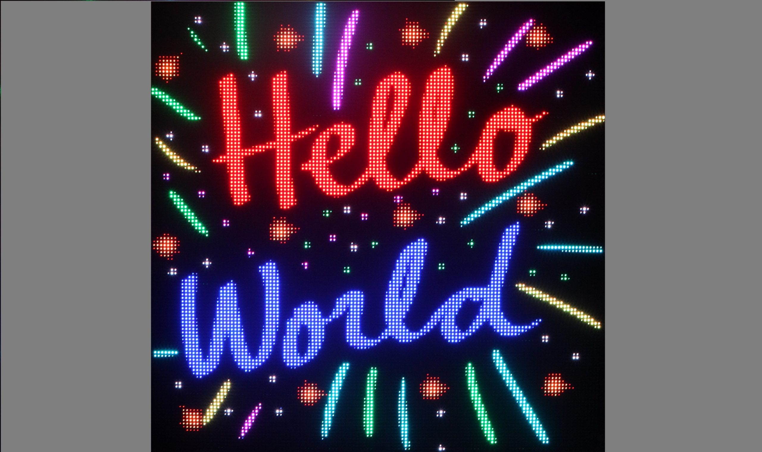
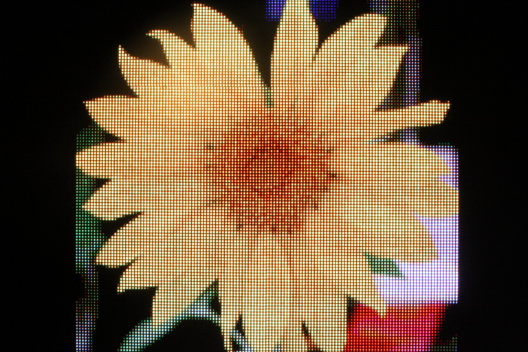
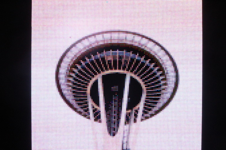
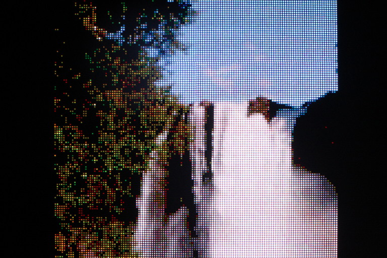
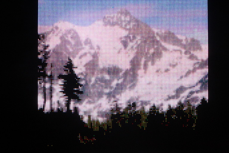
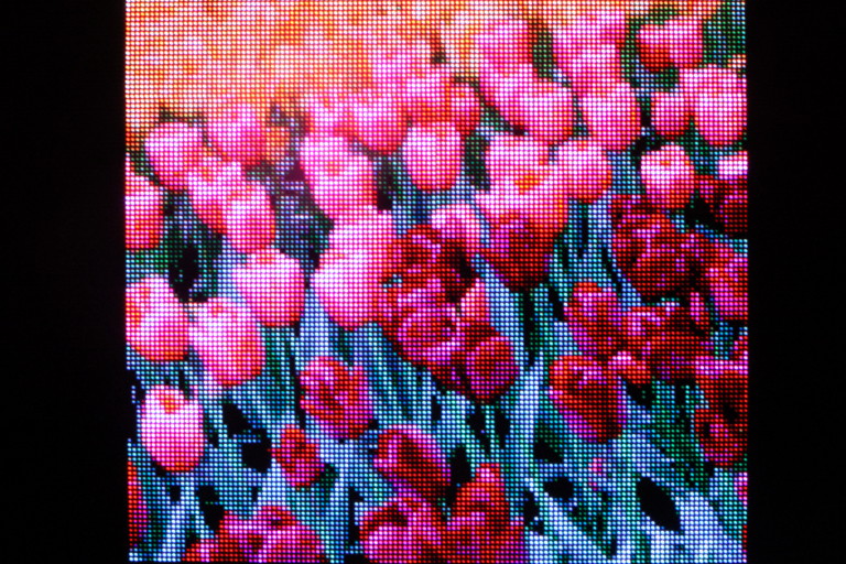
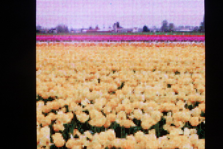
Before we dive in, we have some “Hello world” images from the beautiful Pacific Northwest…
Copyright (C) 2020 Gallium Studio LLC.