Episode 2 Programming Model of LED Panels
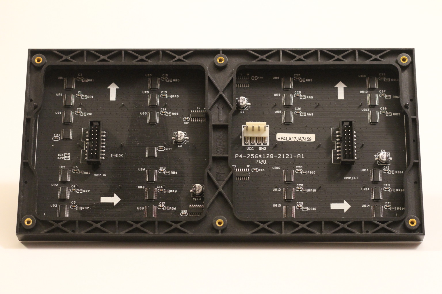
Before we can possibly write any code to control the RGB LED panels, we must understand the control interface to the hardware. Most of these panels share a similar 16-pin control interface. For the 64×32 panels we use, there are 6 RGB data lines, 4 address lines, clock, latch, enable and three ground lines. This type of interface is ubiquitous in digital electronics and has applications in much more sophisticated systems than LED panels.
The panel is divided into two sets, an upper half and a lower half. Each set consists of 16 rows (lines) of LEDs which are selected one by one in a scanning fashion. We call each of these sets a scan set. At any time, only one out of 16 lines is selected, and therefore it is said to have a 1:16 (1/16) scan rate.
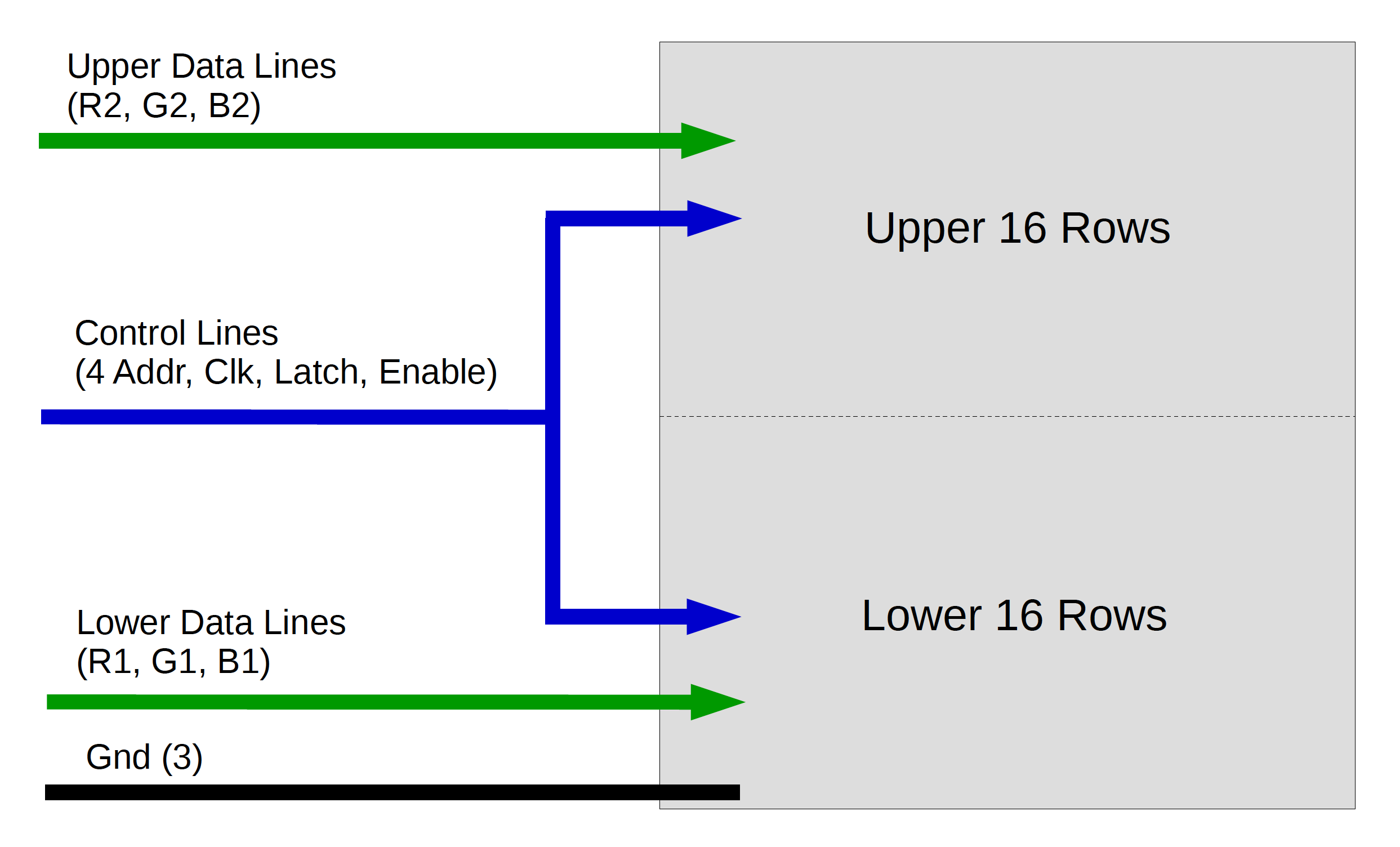
Since there are 16 lines in each scan set, we need 4 address pins to select a line for display (24 = 16). For each set, we need three data lines to individually control the red, green and blue LEDs. In total there are 6 data lines labelled as R1/G1/B1 (lower half) and R2/G2/B2 (upper half). The diagram below illustrates the logical operation of a single data line.
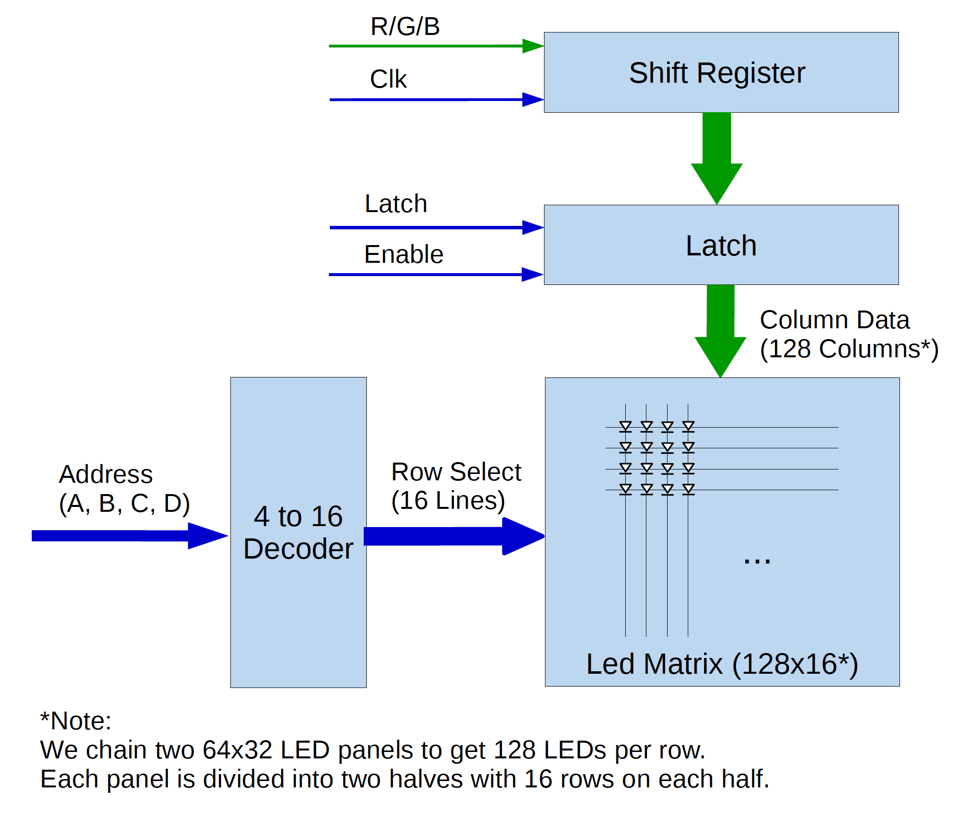
Serial data appearing on an R/G/B data line are shifted into the LED panel via a conceptual shift register. The microcontroller (STM32 / STM32H7 in our design) updates the logic level on the data line on the falling edge of the Clk signal. That logic level (a bit) is then shifted into the shift register on the next rising edge of the Clk. This update-and-shift process is repeated 128 times to load 128 bits of data into the shift register which in essence acts as a serial-to-parallel converter. A high logic level will cause the LED on the corresponding column of the selected row to be turned on; otherwise the LED will be off. Note that the leftmost bit of the serial data shown on an oscilloscope is the first bit shifted in, which corresponds to the rightmost column of the LED panel.
The shift register described above is conceptual because it is physically made up of two 64×32 panels connected together forming a 128×32 unit. Each 64×32 panel in turn contains four 16-bit physical shift registers chained together to form a conceptual 64-bit shift register per color. Later we will see how to drive four of such 128×32 units in parallel to yield a 128×128 panel, thanks to the generous amount of GPIO pins available on an STM32 Nucleo board.
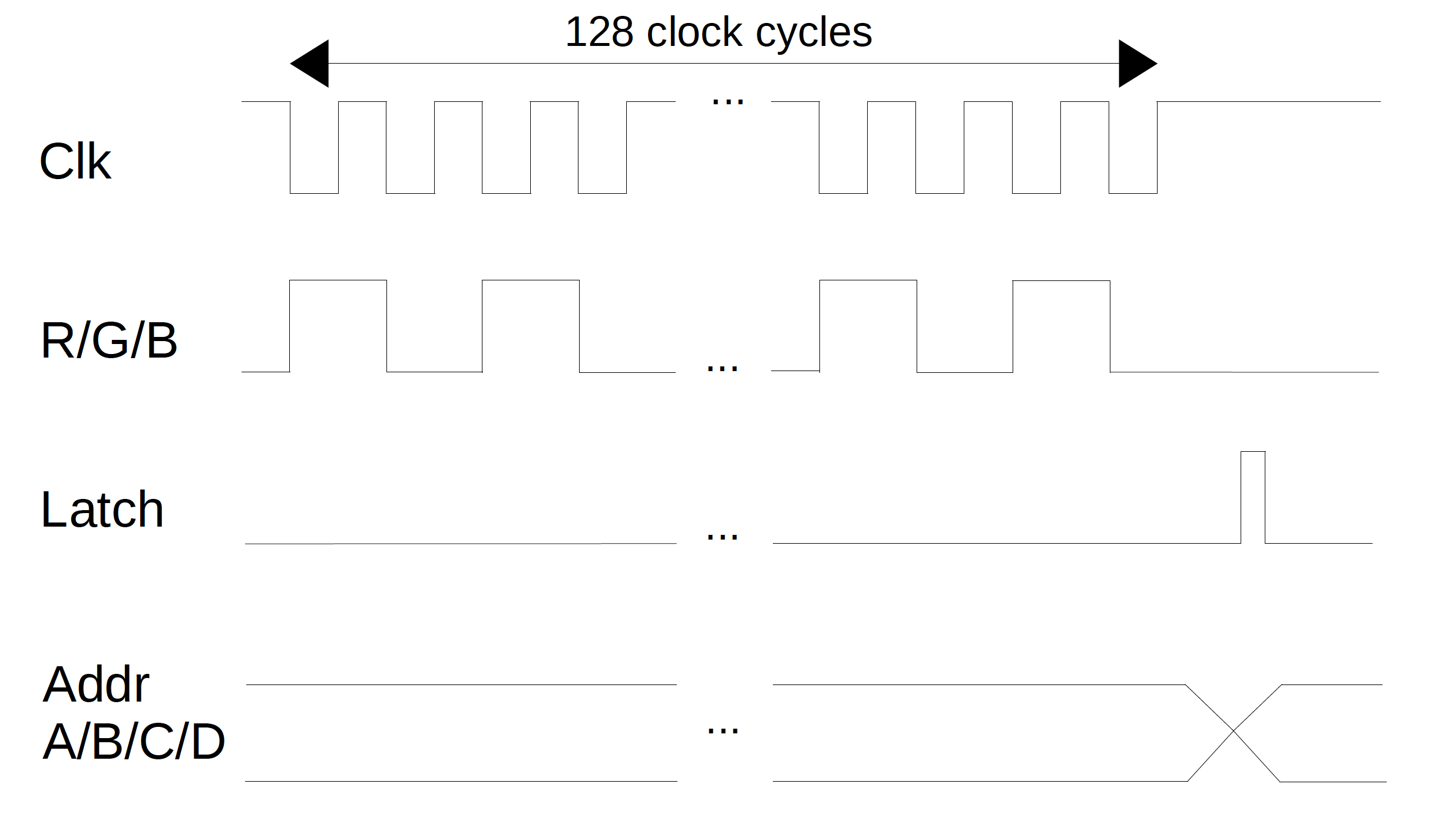
The timing diagram below illustrates the loading of 128 bits of R/G/B data into the shift register. Data loaded into the shift register are not displayed on the LEDs (i.e. not effective) until they are latched via a pulse on the latch pin. This allows new data to be preloaded in the background without affecting the current LED display.
The 4 address lines (A, B, C, D) are used to select one of the 16 rows of LEDs in each half of the panel via a 4-to-16 decoder. For example, if ABCD = 0000b, row 0 is selected. If ABCD = 1100b, row 12 is selected. We can consider these row select lines being active low such that LEDs on the selected row are enabled (forward-biased) while all other rows are disabled. The LEDs on the selected row then shows the bit pattern latched from the shift register. In actual hardware design, the LED direction may be reversed accompanied by internal logic inversion. This is, however, irrelevant to the programming model.
By quickly changing the row addresses and latching the desired bit pattern for each row, an entire image is displayed on the panel. So far we have only described how to generate a binary pattern for each color, i.e. each single-color LED is either turned on or off. Combining the red, green and blue LEDs at each pixel, we can at most get 8 (23) colors. In the next episode, we will learn how to use a variant of PWM (pulse width modulation) to increase the number of colors from 8 to millions.
Copyright (C) 2020 Gallium Studio LLC