Episode 4 Statechart Framework – state
In the last episode, we introduced a statechart describing the behaviors of an alarm clock running on a micro:bit. Its operation is demonstrated in the following video:
Microbit Timer (https://youtu.be/056EfSlMPCY)
Statecharts are more than neat diagrams. Statechart is a visual language that precisely specifies how a system behaves under all possible conditions. It shows us the complete picture, including exception cases and unhappy paths which may otherwise be missed. Statecharts are widely used in industries that demand high reliability such as aerospace and medical devices.
At first glance, the statechart above looks rather busy and we may wonder if statecharts add unnecessary complexity to a design. In fact statecharts simply reveal the inherent details of a design allowing us to analyze the design and ensure it fulfills all the requirements.
Compared to other charts and graphs used in computing, statecharts are especially powerful since given a suitable framework you can directly translate statecharts into executable code. Nowadays statechart frameworks are available for most languages, such as QP and Qt SCXML for C/C++, xstate and SCION for Javascript, PySCXML and miros for Python, etc. For micro:bit, due to its limited memory and Javascript support, it would be tricky to use an off-the-shelf framework. Instead we are going to build from scratch a very simple framework to support key features of statecharts, including hierarchical states, basic orthogonal regions, internal/reminder events, timer events, defer-and-recall, guard conditions, automatic entry and exit actions (limited to leaf states).
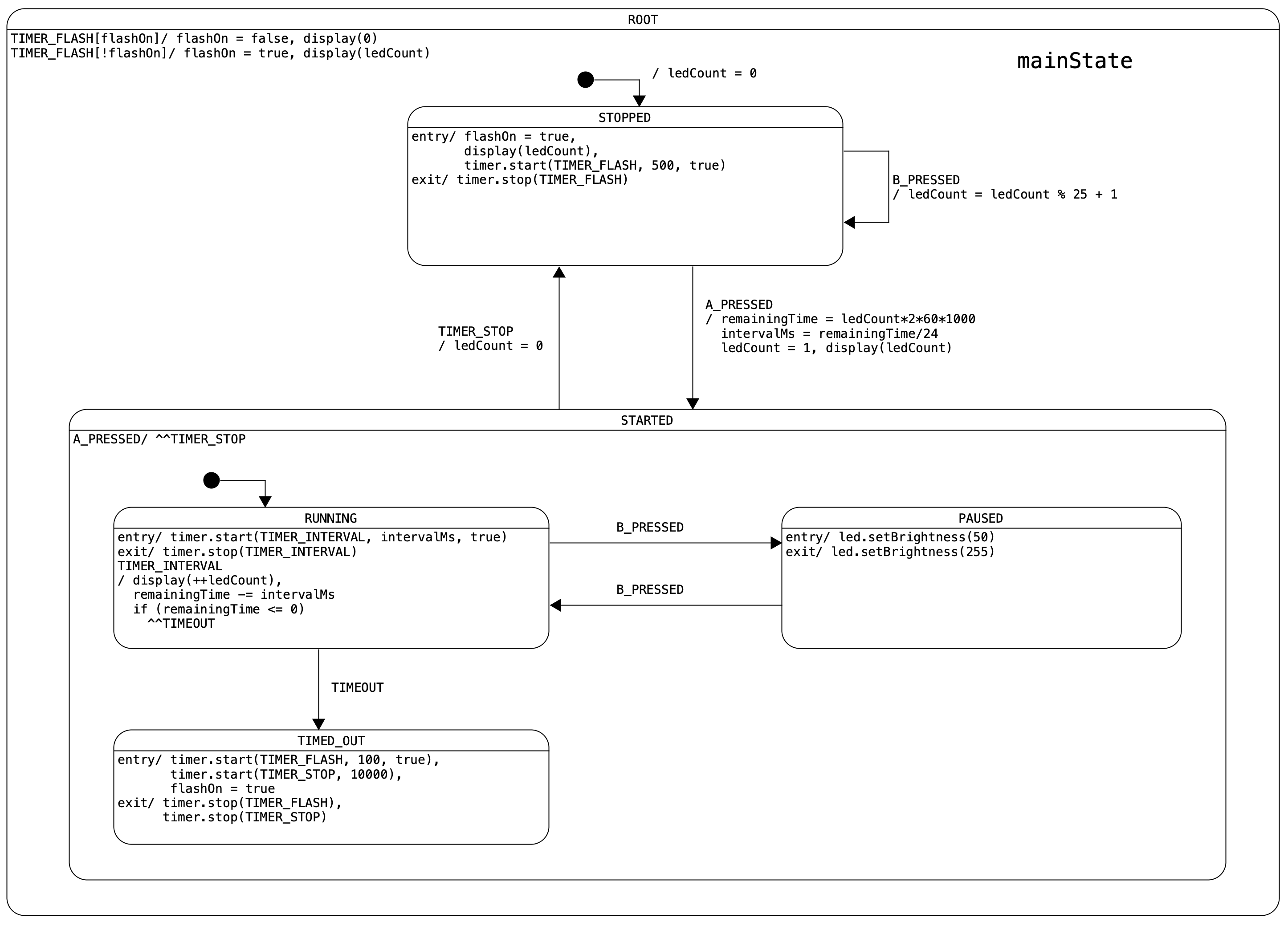
First let’s review the basic statechart notation. A state is represented by a round-cornered rectangle with its name denoted in the upper compartment. A state may contain other states. The containing state is called a superstate or composite state. The contained state is called a substate or nested state. There can be multiple levels of nesting. This is analogous to superclasses and subclasses in object-oriented programming.
When a system is in a composite state, it must also be in one and only one of its substates. In our microbit timer example, since the ROOT state contains the STOPPED and STARTED states, when the system is in ROOT (which it must) it must also be in either STOPPED or STARTED, but not both. (In set theory terms, substates form a partition over its composite state space, i.e. they do not overlap and their union covers the entire space).
The default initial state is indicated by a dark solid dot, called the initial pseudo-state. The arrow (transition) from the dot points to the default substate to go into when a composite state is entered. In our example, the system enters STOPPED by default when ROOT is entered at startup.
In each state, there can be optional entry action and exit action, labeled as:
entry/ action_list
exit/ action_list
Essentially an entry action is the activities to be performed every time when a state is entered, regardless to which path is taken to enter the state. Similarly an exit action is the activities to be performed every time when a state is exited. Statecharts support entry and exit actions in all levels of states, from the topmost composite state to the most-nested leaf state. During a state transition, all exit actions of any states exited and all entry actions of any states entered will be invoked automatically.
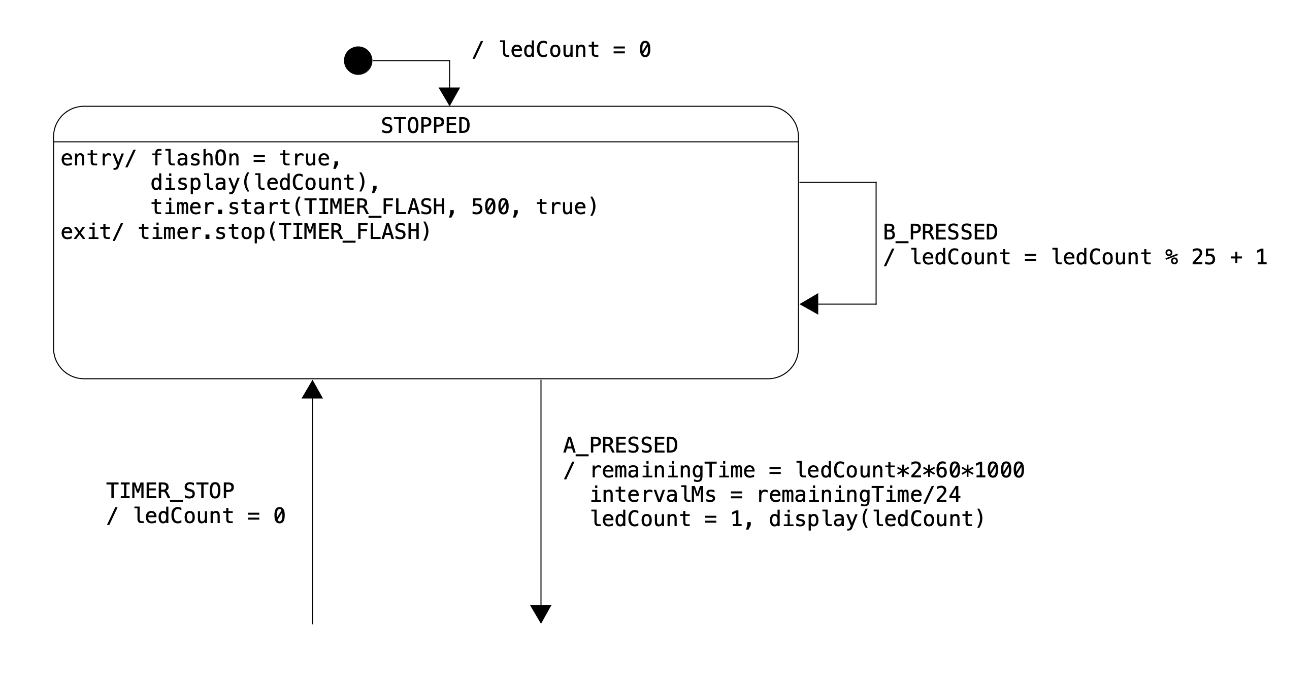
For simplicity our statechart framework only supports entry and exit actions in leaf states. For example, the STOPPED state defines the following entry and exit actions:
entry/ flashOn = true,
       display(ledCount),
       timer.start(TIMER_FLASH, 500, true)
exit/ timer.stop(TIMER_FLASH)
Whenever STOPPED is entered (either by default, from itself or from STARTED) the system will (1) set the flashOn flag to true, (2) display the LED pattern specified by ledCount and (3) start a 500ms timer for flashing. Whenever STOPPED is exited it will stop the timer. This greatly simplifies our design, since the same entry/exit actions are shared by three different transitions. Consider this – when the B button is pressed in STOPPED it simply needs to increment the ledCount and transition to itself. The entry action automatically takes care of updating the display with the new ledCount.
Finally let’s look at some code. Our framework provides a state interface which allows an application to register entry and exit actions for each leaf state. Leaf states are represented by an enum called MainState.
enum Region {
    MAIN,
}
enum MainState {
    STOPPED,
    RUNNING,
    PAUSED,
    TIMED_OUT,
}

state.onEntry(Region.MAIN, MainState.STOPPED, () => {
    flashOn = true
    display(ledCount)
    timer.start(Evt.TIMER_FLASH, 500, true)
})
state.onExit(Region.MAIN, MainState.STOPPED, () => {
    timer.stop(Evt.TIMER_FLASH)
})
Region here refers to orthogonal regions which can be viewed as concurrent state machines. At the moment we don’t need to worry about it since we only have one region called MAIN. The four leaf states in our design, namely STOPPED, RUNNING, PAUSED and TIMED_OUT are listed in enum MainState. The state.onEntry() and state.onExit() function calls specify the entry and exit actions of the STOPPED state.
Comparing the code with the statechart, we can see firstly how our business logic (requirements) about the STOPPED state is represented in the statechart (design) and secondly how the statechart is translated into code. This central concept of directly mapping requirements -> design -> code has been used to build much more complicated systems than a toy timer. (A Mars rover?)